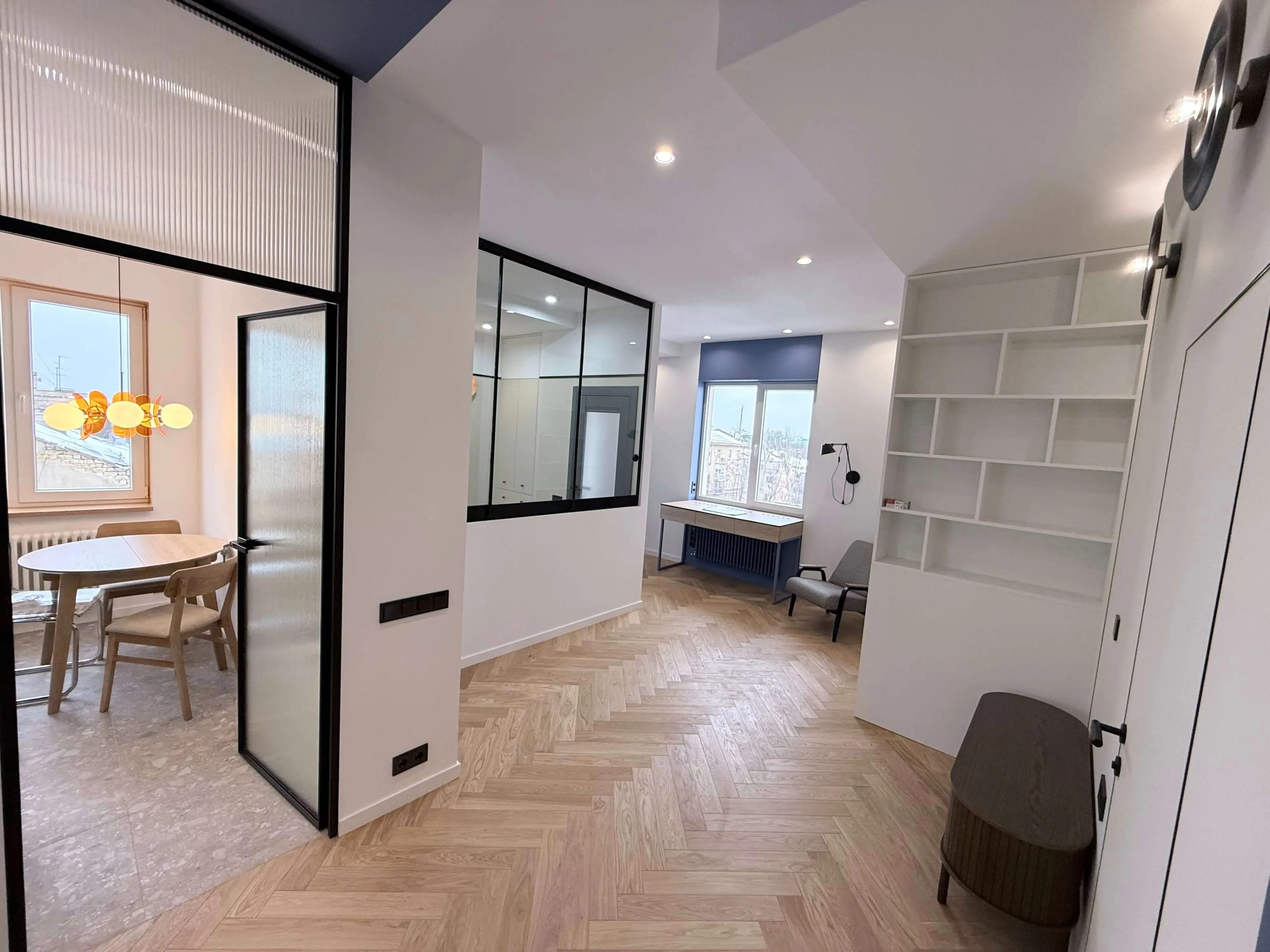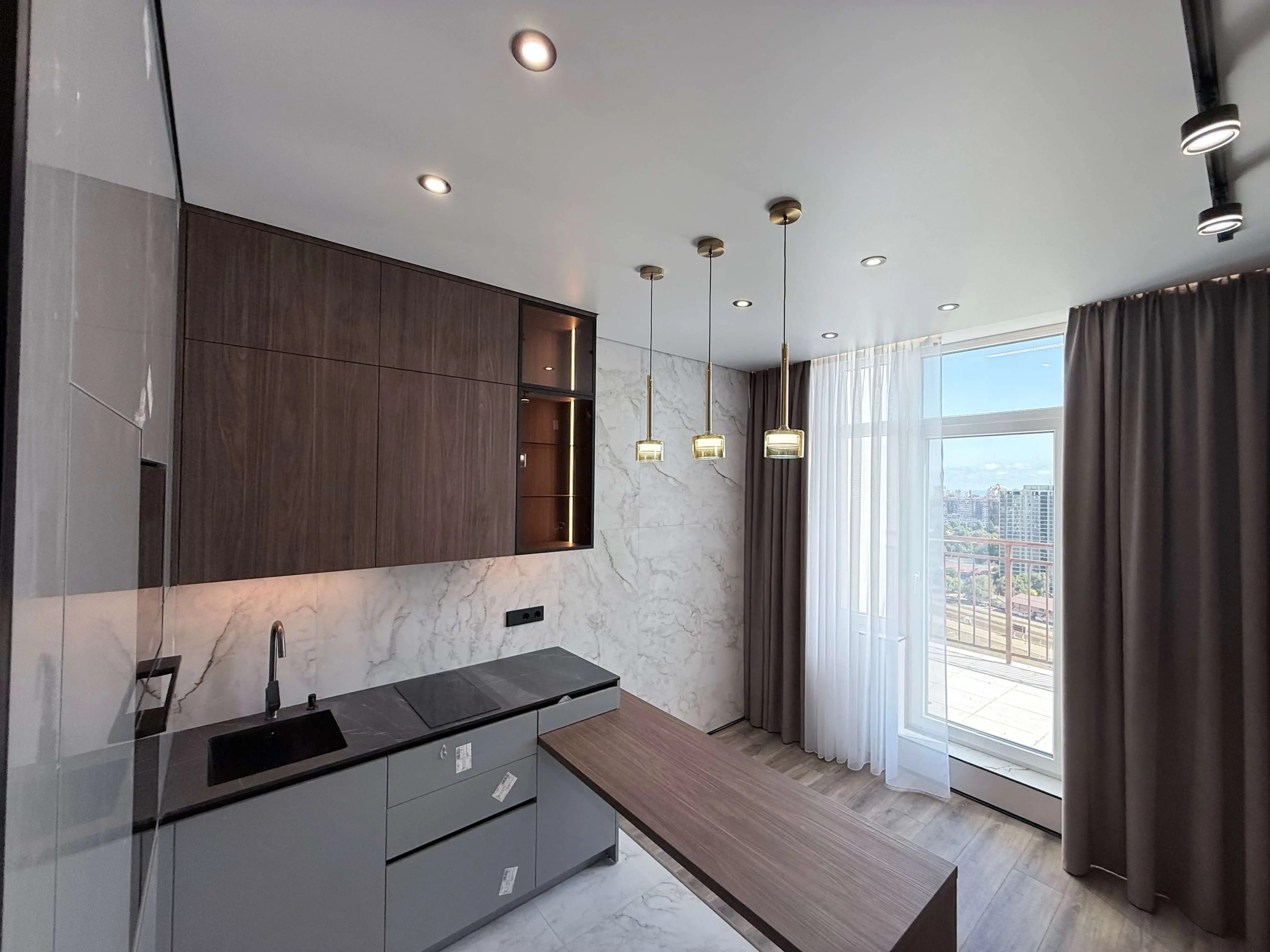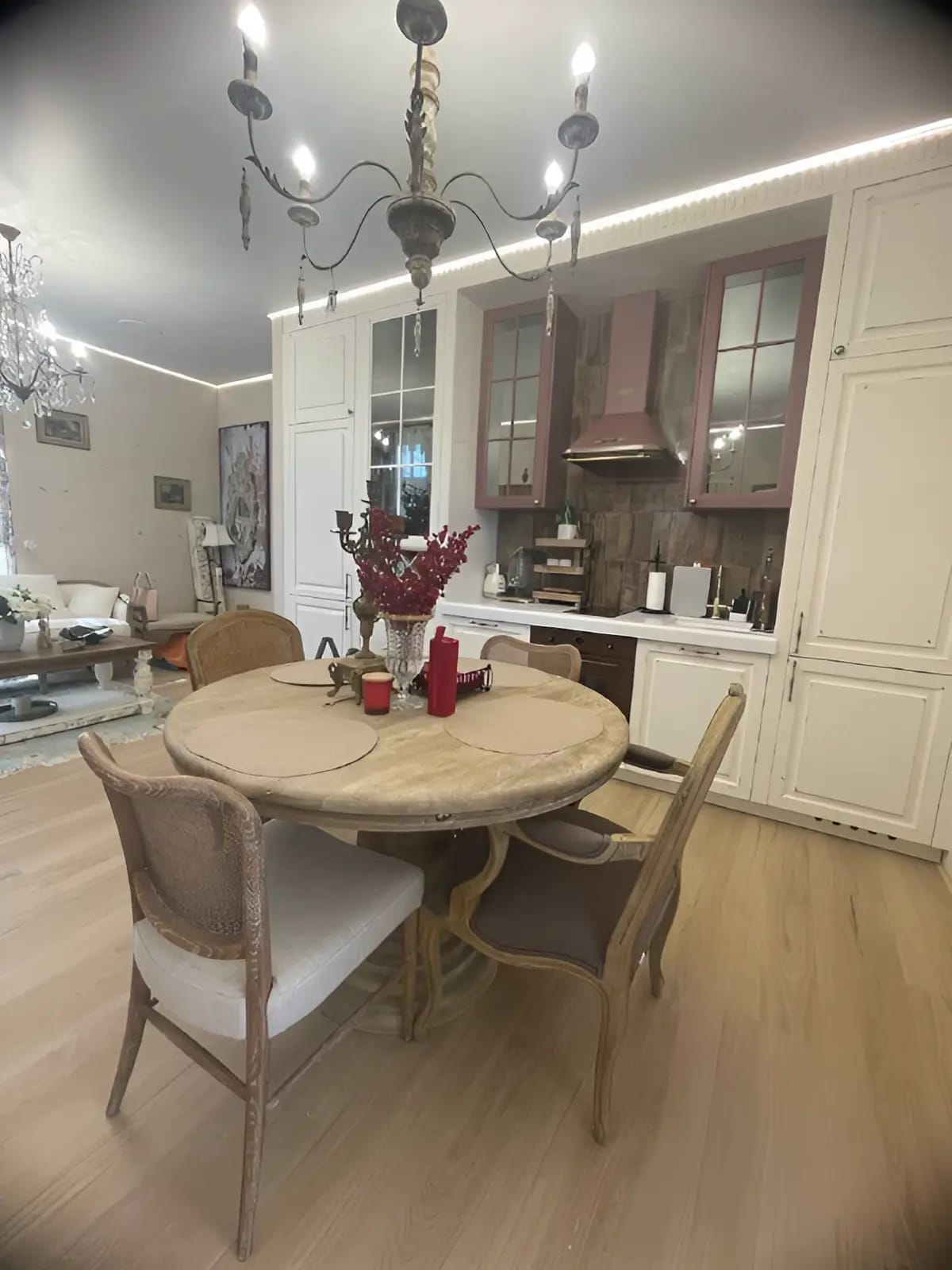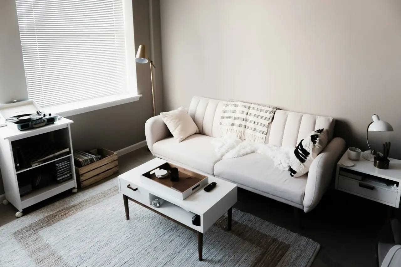
The fit-out and finishing of residential real estate is a strict sequence of engineering and technological processes, where each subsequent layer of materials completely conceals the preceding one. In construction practice, all defects are divided into two fundamental groups: local and systemic. The former includes minor cosmetic imperfections: damaged wallpaper, minor baseboard defects, or misaligned cabinet hinges. Such flaws can be eliminated within a few hours without any significant structural intervention.
Systemic errors committed during the rough-in and rough construction stages are of an entirely different nature. Upon completion of the finishing works, the living space may look immaculate; however, over time, critical failures begin to surface: cracking floor finishes, persistent sewer odors, overheating electrical wiring, or mold growth beneath surface materials. Fixing these problems locally is technically impossible: the only solution is the complete demolition of floor and wall coverings, screeds, or partition walls down to the building's bare structural envelope. Preventing such costly risks is made possible through comprehensive apartment finishing in Lviv, executed under strict engineering supervision at every stage of works subject to covering.
Below is a detailed engineering analysis of the most common critical errors whose rectification inevitably demands full-scale demolition.
1. Plumbing, Heating, and Wastewater Drainage Systems
Mistakes made during the installation of water supply, heating, and sewage systems entail the highest remediation costs, as these utility lines run inside monolithic floor screeds and behind masonry or tiled partition walls clad in porcelain stoneware.
1.1. Violation of Standard Sewage Slopes
Gravity drainage relies entirely on the calculated slope of the piping. According to building codes and standards, the mandatory parameters are:
-
for pipes with a diameter of 50 mm (drains from sinks, bathtubs, showers) — 3 cm per 1 linear meter;
-
for pipes with a diameter of 110 mm (water closet drains) — 2 cm per 1 linear meter.
Both insufficient slope (or reverse slope) and excessive slope are equally critical:
-
With insufficient slope or a counter-slope, the flow velocity drops significantly. Solid particles and grease settle onto the pipe walls, causing chronic clogs that cannot be removed by chemical or mechanical clearing methods.
-
With excessive slope, liquid drains away too rapidly, leaving solid waste behind on the pipe floor. Furthermore, rapid water surges break the trap seal (siphon seal dry-out), allowing toxic sewer gases to escape directly into living spaces.
Once the pipes are encased in concrete or enclosed within gypsum board and tile assemblies, altering their spatial pitch without jackhammering the screed and destroying the tiles is impossible.
1.2. Encasing Demountable Fittings and Maintenance-Required Fixtures
Building codes strictly prohibit the concealed installation of threaded and compression-type fittings. Mechanical connections with rubber O-rings require periodic inspection and tightening, as they lose elasticity over time due to cyclical thermal fluctuations.
Improper socket fusion welding of polypropylene (PPR) pipes is another severe violation. Overheating the material leads to a narrowing of the pipe's internal cross-section (in extreme cases, complete obstruction), whereas underheating creates a weak joint prone to bursting under the first hydraulic shock (water hammer).
A concealed leak inside a partition or floor slab leads to the saturation of the structural slab and the flooding of lower floors. Locating the exact point of failure and repairing it requires the complete opening of the floor or wall.
1.3. Defects in Waterproofing and Walk-In Shower Areas
Constructing an open walk-in shower area without a preformed tray requires complete, seamless watertightness of the substrate. Common critical errors include:
-
absence of elastomeric waterproof sealing tapes at internal "floor-to-wall" perimeter joints;
-
compromised, non-watertight bonding between the linear drain flange and the liquid-applied waterproofing membrane;
-
absence of an adequate slope-to-drain envelope on the shower floor (creating standing water in corners).
Moisture penetrating through tile grout joints saturates the underlying screed. This results in debonding of tiles, adhesive degradation, and mold growth beneath the ceramic surface. Topical application of hydrophobic sealers to grout joints does not solve the root issue: complete demolition of the shower tiles, removal of the waterlogged screed, reapplication of the waterproofing assembly, and retiling are mandatory.
1.4. Underfloor Heating and Central Heating Piping Errors
Routing hydronic underfloor heating loops and radiator supply lines requires strict adherence to thermal expansion rules:
-
Absence of protective corrugated sleeves across screed expansion joints. If a cross-linked polyethylene pipe (PEX/PERT) crosses an expansion joint between screed sections without an elastomeric protective sleeve, the shifting concrete slabs will inevitably pinch, abrade, or shear the pipe over time.
-
Concealing the floor temperature sensor without a smooth-bend rigid conduit. Embedding the temperature probe directly into mortar makes it impossible to pull out and replace once it fails. Restoring floor temperature regulation requires breaking the finish tiles and chipping away the concrete.
-
Running central heating supply pipes without thermal insulation. This leads to uncontrolled, localized overheating of the floor screed along the pipe route, thermal cracking of the finish flooring, and substantial heat losses before water reaches the radiators.
1.5. Lack of Inspection Access to Metering and Filtration Units
Installing miniature access panels or completely tiling over service shafts prevents routine maintenance of pressure-reducing valves, strainers, water meters, and automatic leak-detection shut-off valves. When any internal component fails, service access can only be achieved by tearing down the tiled wall.
2. Electrical and Low-Voltage Networks
Concealed electrical wiring behind plaster or inside suspended ceiling cavities poses significant hazards; failures at this stage directly jeopardize fire safety.
2.1. Mismatched Cable Sizing Relative to Projected Electrical Loads
Using undersized conductors (e.g., 1.5 mm² instead of the mandatory 2.5 mm² for dedicated kitchen receptacle circuits) leads to chronic cable overheating under simultaneous loads from kitchen appliances.
Installing an oversized circuit breaker (to prevent nuisance tripping) causes the conductor's insulation to degrade, melt, and char inside the wall chase. Replacing the damaged or undersized cable requires re-chasing the finished and painted walls along the entire circuit run.
2.2. Inaccessible Junction Boxes with Twisted Wire Connections
Electrical standards strictly forbid bare wire twisting and direct contact between copper and aluminum conductors. Inaccessible branch connections must be executed exclusively by mechanical crimping with ferrules, welding, or brazing.
Unapproved wire connections hidden beneath a layer of plaster oxidize over time, resulting in electrical arcing and elevated contact resistance. When an open circuit occurs, identifying the exact point of failure beneath decorative finishes without wall demolition is impossible.
2.3. Flaws in Equipotential Bonding and Low-Voltage Routing
-
Absence of supplementary equipotential bonding in bathrooms. Metal bathtubs, shower trays, metallic piping, and in-wall carrier frames must be bonded to the main earthing terminal with a dedicated protective conductor of at least 4 mm². Omitting this connection before tile installation prevents the establishment of proper electrical safety standards without running visible surface conduit over completed finishes.
-
Running power lines and network cabling inside the same chase. Routing unshielded twisted pair (UTP) Ethernet cables alongside 230V power conductors without physical separation causes electromagnetic interference, severely degrading network data throughput. Correcting this after plastering requires cutting new wall chases.
2.4. Non-Orthogonal, Diagonal Cable Chasing
Building codes dictate that electrical cabling must be routed strictly vertically or horizontally, maintaining fixed offsets from corners, door/window openings, and ceiling lines. Routing cables diagonally to save wire creates a high risk of puncturing the live conductor with a hammer drill when mounting baseboards, picture frames, shelving, or curtains later on. Repairing a severed conductor requires opening the wall and patching finishes.
3. Floor Screed and Substrate Preparation
The subfloor bears static and dynamic structural loads continuously. Any substrate failure is immediately transferred to the decorative flooring finish above.
3.1. Neglecting Perimeter Expansion Joints and Contraction Cuts
When heated, screeds expand. The absence of perimeter expansion foam tape and the lack of contraction joints across large surface areas generate severe internal compressive stress. The screed fractures, transmitting diagonal cracks straight through the tile adhesive and splitting the porcelain tiles above. Rectifying this defect requires tearing out the tiles and remaking the expansion cuts.
3.2. Non-Compliance with Prescribed Screed Curing Times
A cementitious screed cures and sheds moisture at a rate of roughly 1 cm of thickness per week under standard temperature and humidity conditions. Installing hardwood flooring, laminate, or luxury vinyl tiles over a screed with residual moisture exceeding 2% traps water vapor beneath an impermeable underlayment. Solid and engineered wood warps irreversibly, requiring complete disposal of the flooring and prolonged drying of the interior.
4. Wall Geometry, Partition Assembly, and Door Joinery
Geometrical misalignments cannot be masked by decorative painting or trim work.
4.1. Lack of True 90-Degree Right Angles in Critical Areas
Plastering walls flat without squaring them to 90 degrees is a fatal mistake in functional zones:
-
Kitchen worktops: An angular discrepancy of even 2–3 degrees leaves an unsightly wedge-shaped gap of several centimeters between the rectangular countertop and the wall, preventing proper cabinetry alignment.
-
Bathrooms: A rectangular bathtub or shower base cannot fit flush against out-of-square walls, leaving deep gaps where water consistently pools and bypasses silicone seals.
-
Built-in wardrobes: Out-of-square recesses cause sliding door mechanisms to bind and create uneven gaps against surrounding side panels.
Correcting out-of-square corners using thin-coat finishing compounds after plastering is impossible due to excessive thickness requirements; the existing plaster must be stripped back to the bare brickwork and reapplied using laser-aligned screed guides.
4.2. Structural Violations in Partition Construction
Laying aerated concrete block partitions without flexible anchor ties to load-bearing columns, and without a compressible deflection gap beneath the upper structural slab, results in horizontal cracking when the floor slab above deflects under load.
In lightweight drywall systems, using sub-standard metal studs with steel thicknesses under 0.6 mm, omitting horizontal noggins/transoms, or extending stud spacing beyond 60 cm compromises rigidity. The wall vibrates whenever doors close, resulting in chronic joint cracking and tile debonding. Reinforcing an assembled partition from within is impossible; it must be taken down and framed anew.
4.3. Installation Errors with Concealed-Frame Doors and In-Wall Cisterns
Modern architectural solutions demand millimeter-accurate execution:
-
Concealed-frame (flush-to-wall) doors. Aluminum sub-frames must be installed prior to wet plastering, taking the exact final floor build-up into account. If the finished plaster surface protrudes past the frame face by even 1–2 mm, the door leaf will bind and scratch the wall. Fixing this requires hacking away the plaster surrounding the entire opening or dismantling the sub-frame.
-
Mounting elevation of in-wall WC carrier frames. Securing the carrier frame before pouring the screed without accounting for the complete floor assembly (soundproofing, screed, tile adhesive, porcelain stoneware) causes the toilet bowl to sit either too low (25–30 cm off the floor instead of the standard 40–43 cm) or excessively high. Correcting the mounting height requires tearing out the gypsum box and breaking away the tile cladding.
5. Ventilation, Air Conditioning, and Acoustic Insulation Details
5.1. Constriction or Obstruction of Natural Gravity Ventilation
Connecting a high-capacity range hood (rated for 800–1000 m³/h) directly into a communal passive ventilation shaft (designed for a maximum airflow of 60–90 m³/h) creates backpressure that forces cooking odors into neighboring apartments. Furthermore, when the range hood is switched off, its internal backdraft damper completely halts natural air exchange in the kitchen. Remedying the ducting requires tearing down suspended ceilings and cabinetry.
5.2. Hidden Defects in Refrigerant Lines and Condensate Drain Lines
Concealing air-conditioning copper line sets inside walls without prior hydrostatic or dry-nitrogen pressure testing risks rapid refrigerant loss through micro-fissures hidden beneath plaster.
Failure to maintain the minimum required pitch on condensate gravity drain lines (at least 1–2 cm per meter) leads to water backing up and overflowing inside the indoor unit, soaking painted walls. Remediation requires cutting chases across the entire length of the concealed line.
5.3. Acoustic Bridges in Soundproofing Systems
Installing soundproofing linings on walls and ceilings without proper mechanical decoupling negates the acoustic performance of high-grade materials:
-
fastening metal framing directly to concrete slabs using rigid metal anchors instead of resilient acoustic isolation mounts;
-
omitting perimeter acoustic isolation tape beneath track profiles;
-
creating rigid contact points between plasterboard sheets and flanking walls without leaving an expansion perimeter sealed with non-hardening acoustic mastic.
Through such flanking sound bridges, impact and structure-borne noise bypasses the soundproofing barrier entirely, causing the suspended structure to resonate like a drum. Removing structure-borne vibrations requires dismantling the entire ceiling or wall assembly and rebuilding it on certified acoustic isolation hangers.
6. Quality Control Protocols for Concealed Works
The occurrence of defects that cannot be rectified without demolition stems primarily from the absence of intermediate quality control procedures and fragmented responsibility among disjointed trades. Preventing demolition relies on strict technical benchmarks:
-
Comprehensive working drawings. The project documentation must contain detailed partition layouts, coordinated electrical runs, wall elevations showing plumbing stub-out dimensions, finished floor level datum marks, and mounting specifications for concealed frames.
-
Mandatory acceptance testing and commissioning:
-
hydrostatic pressure testing of potable water and hydronic heating systems at 8–10 bar for a minimum of 24 hours prior to screed pouring;
-
verification of sewage pipe slopes using digital levels and full-flow drainage testing;
-
pressure testing of air-conditioning copper lines with dry nitrogen at 30–40 bar;
-
insulation resistance testing of all electrical circuits using a calibrated megohmmeter before sealing chases;
-
flood testing of wet-area waterproofing membranes by pooling water for 24 hours.
-
-
Photographic and as-built dimensional recording. Capturing comprehensive, scaled photographs of all rough-in installations referenced against structural corners and door frames before surfaces are closed up.
Avoiding chaos and finger-pointing among independent subcontractors is best accomplished through professional turnkey finishing, where a single general contractor assumes full legal and contractual responsibility for the entire engineering cycle. Under the operational standards maintained by RSU company, every phase of work subject to covering is formally inspected and documented in an acceptance certificate. This systematic approach ensures that no technical failure will ever necessitate jackhammering freshly completed living spaces.